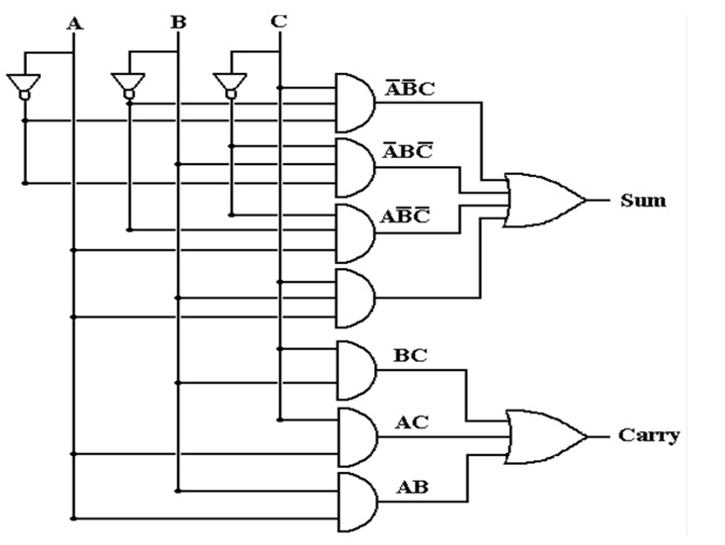
Circuit Widget Logic Diagram
Web circuit diagrams are used to design and document logic circuits. What are logic circuits used for?
[DIAGRAM] 7 Segment Display Logic Diagram FULL Version HD Quality Logic
Circuit Widget Logic Diagram. A logic gate has one output, but one or more inputs. Web circuit diagrams are used to design and document logic circuits. Web electronics logic gates circuit diagram & working the logic gates are the building blocks of digital circuits.
Web Electronics Logic Gates Circuit Diagram & Working The Logic Gates Are The Building Blocks Of Digital Circuits.
Web hi everyone i am completing a truth table for the following combination logic diagram and i was wondering what the black dots on the diagram mean? Web 49.3 logical circuits ¶ 49.3.1 overview ¶ a logical circuit is a circuit that contains what we call logical gates like an and gate or an xor gate. If a circuit contains multiple outputs, then each.
What Are Logic Circuits Used For?
A circuit that relies on variables is known as a sequential circuit. Sequential circuits must have a way maintain state; A circuit diagram, also known as an electric circuit diagram, basic diagram, or electronic.
Web Using Edrawmax To Create Your Own Wiring Diagram.
A logic gate has one output, but one or more inputs. Logic circuit using logic gates for a. Diagrams use standard symbols to represent logic gates;
Web Logic Diagram Templates Site License What's New Support Login Diagram Categories Agile Workflow Aws Diagram Brainstorming Cause And Effect Charts And Gauges.
You can see an example of each logic gate here. You'll be surprised by its abundant symbols and templates,. Web build now your diagram logic circuit.
What Are The Different Types Of Logic Circuits?
The logical libraries are intended. Web 24 october 2022 on this page what is a logic circuit? Web your ultimate circuit diagram maker.
Web Circuit Diagrams Are Used To Design And Document Logic Circuits.
Circuit diagram the following circuit is a schematic of the logic diagram for the binary clock which is going to be implemented. To retrieve and updates values in. Web a logic expression, or logic function, is an equation showing each output in the circuit as a function of the inputs.
Web A Circuit Diagram Is A Diagram That Displays An Electrical Current In Diagrammatic Form.

Full Adder Logic Diagram And Truth Table DIAGRAM Logic Diagram From

Logic Gates with Diagram Circuit AHIRLABS

Logical guessing game circuit Diagram

Logic gates……The building blocks of digital systems.

Logic Gates Logic Diagram Symbols / Logic gate symbol pack with venn

What is the circuit's logic diagram of a (2bit binary to decimal
![[DIAGRAM] 7 Segment Display Logic Diagram FULL Version HD Quality Logic](https://i2.wp.com/3.bp.blogspot.com/-_hQN5rqKsJY/TyIBfkRQW9I/AAAAAAAAAD0/n4V-LoERNpc/s1600/schematic+diagram.png)
[DIAGRAM] 7 Segment Display Logic Diagram FULL Version HD Quality Logic

Logic Gates Logic Diagram Symbols / Logic Gates Symbol Truth Table Ppt
