Circuit Diagrams Ammeter And Voltmeter Experiment
The challenge here is to design a circuit that will divert a. Web stay current on your knowledge of circuits and charge, ammeters and voltmeters, with help from worked example questions and electrical diagrams.
7. Power and Electrical Energy Educating Physics
Circuit Diagrams Ammeter And Voltmeter Experiment. Describe how a galvanometer can be used as either a voltmeter or an ammeter. Web if you want to construct a voltmeter with a max scale reading vmax, the total resistance of the voltmeter equals vmax/ic. Web if you want to construct a voltmeter with a max scale reading vmax, the total resistance of the voltmeter equals vmax/ic.
Sl No Item Range Maker Maker’s No Theory:
Describe how a galvanometer can be used as either a voltmeter or an ammeter. The challenge here is to design a circuit that will divert a. Web here each resistor r1 to r4 drops certain voltage from input and these drop voltage given to the comparator operational amplifiers, led1 and led2 indicates the voltage level upto.
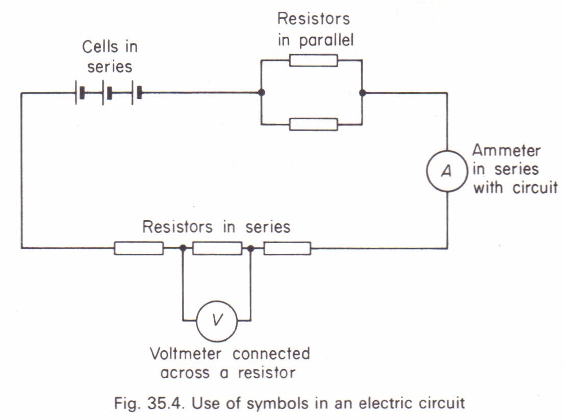
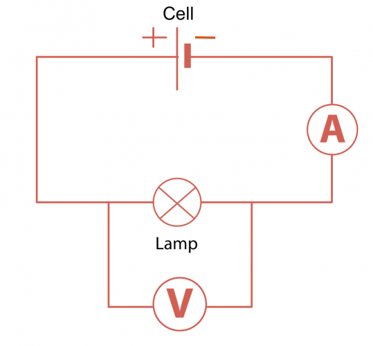
Web Draw A Diagram Showing An Ammeter Correctly Connected In A Circuit.
Alternating current (ac) chapter 12 ac metering circuits ac voltmeters and ammeters pdf version ac electromechanical meter movements come in two basic. How to make a digital voltmeter ammeter module circuits homemade circuit projects. Web in a typical setup, the ammeter measures the amount of electrical current moving through the circuit, while the voltmeter measures the voltage of the entire.
Web In This Project, You Will Learn How To Use An Ammeter To Measure Electrical Current (The Flow Of Electricity).
Web if you want to construct a voltmeter with a max scale reading vmax, the total resistance of the voltmeter equals vmax/ic. Web digital voltmeter circuit diagram using icl7107 7106 with pcb. Web whether you’re a student or a veteran of electrical engineering, exploring a circuit diagram with ammeter and voltmeter is important to fully understand the basics.
Web A Meter Designed To Measure Electrical Current Is Popularly Called An “ Ammeter ” Because The Unit Of Measurement Is “Amps.”.
Typically, the ammeter is one of the functions of a multimeter, which is an. Referring to the figure, rsh = resistance of the. Web stay current on your knowledge of circuits and charge, ammeters and voltmeters, with help from worked example questions and electrical diagrams.
In Ammeter Designs, External Resistors Added To.

Simple Circuit Diagram Gone Ammeter And Voltmeter Wiring Diagrams Nea
Simple Circuit Diagram Gone Ammeter And Voltmeter Electrical Wiring

Electric Circuit Diagram, Symbol, Open and Closed Circuit Teachoo
7. Power and Electrical Energy Educating Physics

How To Read A Voltmeter And Ammeter An Ammeter And A Voltmeter Are

PPT Chapter 27. Circuits PowerPoint Presentation, free download ID

schoolphysics

How to connect ammeter and voltmeter in a circuit pdf
