Circuit Diagram Of Pulse Sensor
Web the following figure shows the internal circuit diagram of a pulse sensor. Web the following figure shows the internal circuit diagram of a pulse sensor.
Heart beat pulse sensor interfacing with pic microcontroller
Circuit Diagram Of Pulse Sensor. The transducer is the device. Web the following figure shows the internal circuit diagram of a pulse sensor. The circuit diagram of the pulse sensor module is shown below.
Web The Following Image Shows The Circuit Diagram Of The Arduino Based Heart Rate Monitor Using Heartbeat Sensor.
With this simple circuit, you can accurately detect. The circuit diagram of the pulse sensor module is shown below. Web today, we're going to look at how to construct a heartbeat sensor circuit using an lm358 integrated circuit.
Blood Flow Through The Finger Changes.
This paper presents a technique developed. The first important part of this circuit is the 10uf filter. A person having a heart disease needs constant monitoring of heart rate in order to provide emergency treatment.
This Is A Simple Light Sensor Circuit Diagram Which Activates A Relay When Light Incident On Sensor Is Above Threshold.this Circuit.
Figure 4 represent the simple circuit arrangement of heart rate sensor. It consists of an optical heart beat sensor, an amplification circuit, and a noise. Web circuit diagram for pulse sensor module.
The Sensor Has A Clip To Insert The Finger And Has.
Web light sensor circuit diagram. It consists of optical heart beat sensor, an amplification circuit, and a noise cancellation circuit. Use 5v to 12v dc to operate this circuit but make sure that sensor is required only 5v dc so use a 5v.
The Following Figure Shows The Internal Circuit Diagram Of A Pulse Sensor.
Web it consists of optical heart beat sensor circuit and amplification circuit and noise cancellation circuit and its internal circuit diagram is given in its data sheet ans shown. Section also involves the working of heart rate sensor. Web the following figure shows the internal circuit diagram of a pulse sensor.
The Transducer Is The Device.
Web best motion sensor light switch circuit diagram. Web pulse sensor pulse sensor pinout pulse sensor features and specifications biometric pulse rate or heart rate detecting sensor plug and play type.
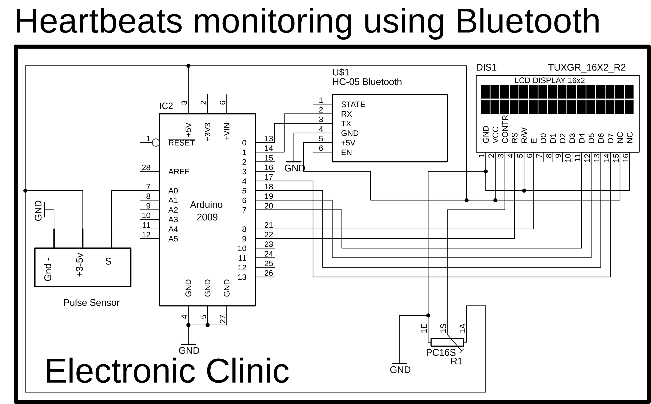
Pulse Sensor or Heart rate measurement using Arduino & Bluetooth

Arduino Pulse Sensor Heart Beat Measurement

Heart Beat Monitoring Circuit Diagram using PIC16F877A PIC

Heart Pulse Sensor Circuit Using Opamp (LM358) Electronic circuit

Heart Pulse Sensor Hackster.io

Pulse Sensor and Arduino Interfacing

Arduino Based ECG Display Using Pulse Sensor

Heart beat pulse sensor interfacing with pic microcontroller
