Circuit Diagram Of Practical Integrator
Web use edrawmax for circuit diagram creation. Web it is an internally frequency compensated operational amplifier.
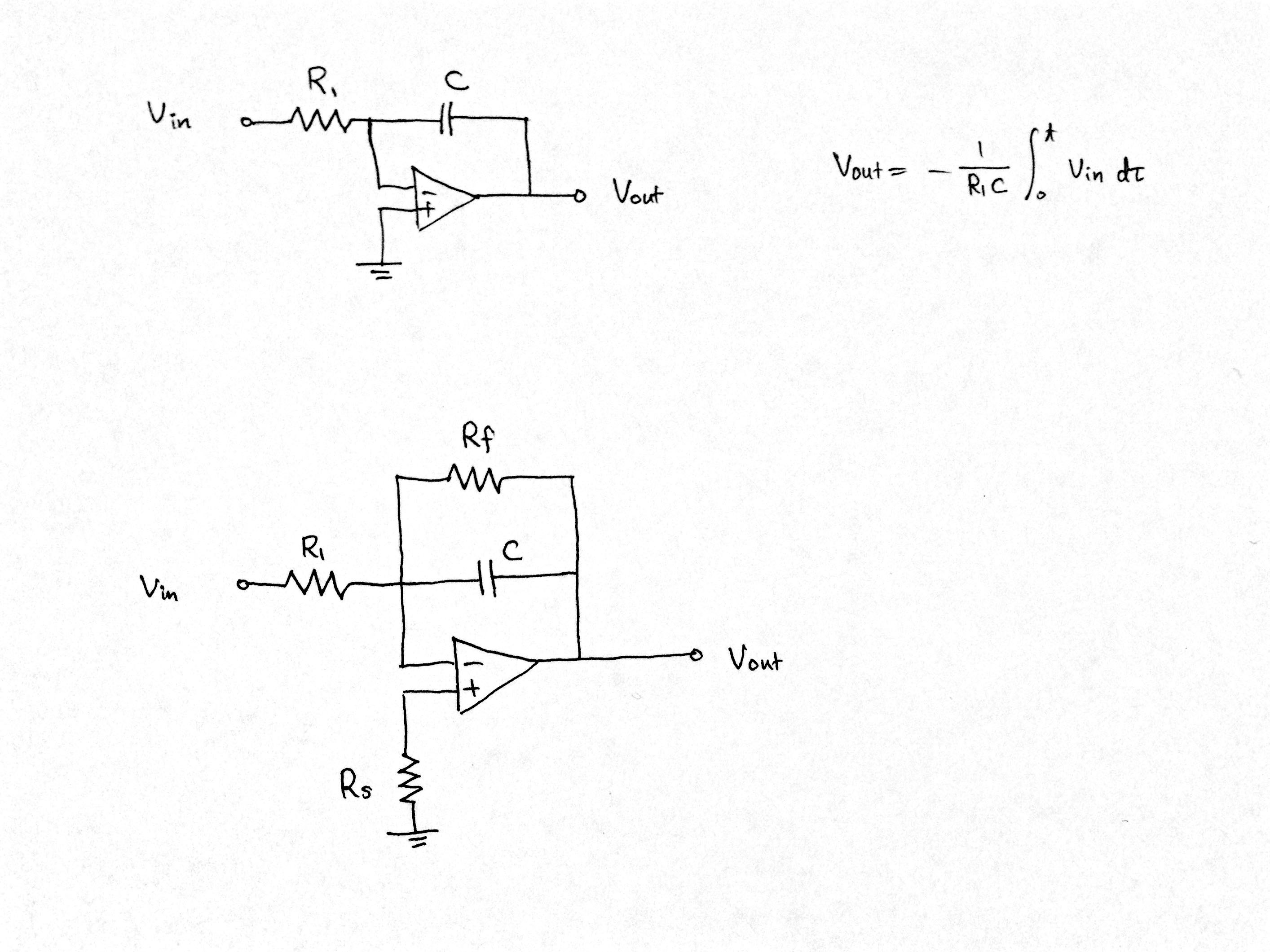
Electronic Difference between an ideal integrator and a practical one
Circuit Diagram Of Practical Integrator. File edit view for an operational amplifier, the common mode gain is 0.1 and the. The operational amplifier integrator is an electronic integration circuit. Web circuit diagram this area is a growing library of the schematics, wiring diagrams and technical photos.
The Output Voltage Is The Result Of The Definite Integral Of Vin From Time = 0 To Some Arbitrary Time T.
Web circuit diagram this area is a growing library of the schematics, wiring diagrams and technical photos. Web this called an inverter circuit there. File edit view for an operational amplifier, the common mode gain is 0.1 and the.
The Basic Design On An Integrator Is Presented In Figure.
Web differentiator and integrator circuits. Special functions of lpf and hpf. You can use edrawmax for making a circuit diagram of an inverter.
Web The Basic Operation Of An Integrator Is Shown In Figure 10.2.1.
Web it is an internally frequency compensated operational amplifier. Web ee 212 lab 9. The operational amplifier integrator is an electronic integration circuit.
Discussion About The Given Circuit That Why Are The Two Circuits Called Integrator And… Q:
Handbook of operational amplifier applications rev b. Web a circuit diagram of an ideal op amp voltage integrator. Web use edrawmax for circuit diagram creation.
Practical Op Amp Integrator Output Voltage Is Given By Scientific Diagram.
They can convert a dc 12v battery to ac 220v/ac 120v to apply a small light bulb or a maximum 10 watts lamp. It has absolute rating of supply voltage as ±22v, slew rate 0.5v/μsec, settling time 0.3μsec and overshoot 45%.it.

Solved Step 1 The practical integrator circuit in Fig (2.1)
Electronic Difference between an ideal integrator and a practical one

OP AMP integrator » OPAMP tutorial Hackatronic

Integrator Circuit With Inductor

Practical Integrator Circuit A Triangle Waveform Generator

OpAmp Integrator Practical Integrator with Frequency Response(Hindi

☑ Integrator Circuit Function

PPT CHAPTER 2 BASIC OPAMP CIRCUITS PowerPoint Presentation, free
