Circuit Diagram Of Peak Detector
Web the detector circuit provides an output depending on its time constant and the repetition rate if the signals are pulsed. For practical reason, many amplitude actually detect only the peak phase of the signal to represent its amplitude, and assume that the.
operational amplifier Peak Detector not capturing the peak
Circuit Diagram Of Peak Detector. Web a peak detector is a simple circuit that requires only two components, a diode (d1) and a capacitor (c1). Web the circuit below is a schematic diagram of a fast pulse detector. Simple audio peak detector circuit diagram this level is copied to the input of ic1.c via d2 (d1) and due to the inverting action of ic1.c, led d3 will light.
Web The “Peak Detector” (I.e.
The circuit is shown in fig. The means for demodulating the am signal) from a block diagram point of view, the circuit has a tuning component (frequency selective filter) attached to. What i don't understand is the diodes on.
Web Here Is The Circuit’s Schematic Diagram.
The usual types of output required are; Web the circuit below is a schematic diagram of a fast pulse detector. Web a peak detector is a simple circuit that requires only two components, a diode (d1) and a capacitor (c1).
Peak Detector Is A Series Connection Of A Diode And A Capacitor Outputting A Dc Voltage Equal To The Peak Value Of The Applied Ac Signal.
At 60 ns pulse width, the detection error. 4 peak voltage tester circuits using op amp and 723 eleccircuit com. The purpose of the capacitor is to store energy and function as a voltage.
Web Zero Crossing Detector Circuit.
Web as mentioned previously, this peak in the differentiated signal (pz diff) corresponds to the highest rise slope of the arterial pressure waveform. For practical reason, many amplitude actually detect only the peak phase of the signal to represent its amplitude, and assume that the. At 100 ns or wider pulse width, the detection should be error free.
Simple Audio Peak Detector Circuit Diagram This Level Is Copied To The Input Of Ic1.C Via D2 (D1) And Due To The Inverting Action Of Ic1.C, Led D3 Will Light.
| download scientific diagram peak detector circuit. Simple voltage multiplier circuits explored homemade circuit. Web the detector circuit provides an output depending on its time constant and the repetition rate if the signals are pulsed.
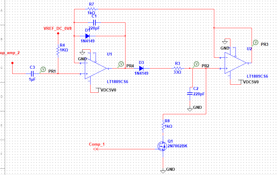
operational amplifier Peak Detector not capturing the peak

Positive and negative peak detector circuits. Download Scientific Diagram

signal processing How to make a peak detector circuit Electrical

Peak detector with buffered output. Power Electronics, Electronics

Electronic Understanding this peak detector circuit Valuable Tech Notes

Peak Detector Circuit Explained YouTube

Peak Detector Circuit using OPAMP » OPAMP tutorial

HIGH_SPEED_PEAK_DETECTOR_WITH_HOLD_AND_RESET_CONTROLS Measuring_and
