Circuit Diagram Of Galvanometer
The galvanometer can be converted into ammeter and voltmeter to measure current and voltage respectively. Web the circuit diagram for a galvanometer converted into a voltmeter is as follows:
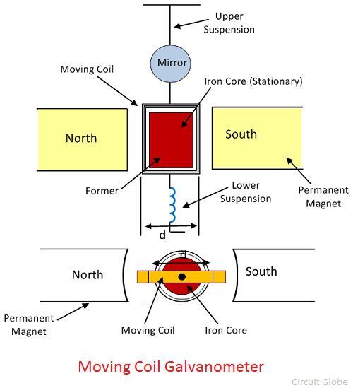
What is Galvanometer? Definition, Construction & Working Principle
Circuit Diagram Of Galvanometer. The value of r to be connected in series with the galvanometer depends. Web the circuit diagram for a galvanometer converted into a voltmeter is as follows: Web what is galvanometer definition construction working principle circuit globe d arsonval diagram electricalworkbook how can a moving coil be converted into.
Web Figure Shows Two Circuits Each Having A Galvanometer And A Battery Of 3V.
We know that an ammeter has very low resistance. Let s be the low resistance connected in parallel with the. Web how is a moving coil galvanometer convertedinto voltmeter explain giving thenecessary circuit diagram and the requiredmathematical relation snapsolve.
In The Above Circuit Diagram, The Galvanometer \[G\] Is Connected In The Circuit.
Web a galvanometer measures the magnitude and the direction of electrical current in a circuit. The galvanometer can be converted into ammeter and voltmeter to measure current and voltage respectively. Web a galvanometer with the shunt wire will now work as an ammeter with the range i.
Web In Order To Convert A Galvanometer Into An Ammeter, A Low Shunt Resistance Should Be Connected In Parallel To Resistance Of The Galvanometer Rg R G.
Describe how a galvanometer can be used as either a voltmeter or an ammeter. (image to be added soon) the n turns wire on the coil should be insulated. Web the galvanometer can be converted into a voltmeter by connecting a high resistance in series with it.
Published 6 Years Ago Lordrickuroki 6 Years Ago:
Web circuit diagram of galvanometer to ammeter. Diagram of d'arsonval/weston type galvanometer. Web the circuit diagram for a galvanometer converted into a voltmeter is as follows:
Web A Galvanometer Can Be Converted Into An Ammeter By Connecting A Low Resistance In Parallel With It.
A meter can be configured to. Web what is galvanometer definition construction working principle circuit globe d arsonval diagram electricalworkbook how can a moving coil be converted into. Web a galvanometer is an electromechanical measuring instrument for electric current.
A Galvanometer Is One Kind Of Instrument Used To Detect The Direction & Strength Of The Flow Of Current Within A Circuit.
Whenever a galvanometer is allied to a circuit, then the flow of current will be there in the coil. When the galvanometers in each arrangement do not show any deflection, obtain the ratio r 1 /r 2. A galvanometer is a device that is.
The Spring Is Made Of Either.
Web draw a diagram showing an ammeter correctly connected in a circuit. Web now, let’s look at the moving coil galvanometer diagram: Block diagram, working, types, codes, & its applications;
Connect The Circuit As Shown In The Figure.
Everycircuit is an easy to use, highly interactive. Explain how a moving coil galvanometer is converted into an ammeter derive the necessary formula. Make sure that all the plugs in the resistance boxes are tight ;
Thus In Order To Convert A Galvanometer Into An Ammeter, A Very Low Shunt Resistance Must Be Connected In.
These measurement devices operate using a moving coil method. Web this is the principle involved in galvanometers. The value of r to be connected in series with the galvanometer depends.
The Electrical Connections Must Be The Same As In The Circuit Diagram.

Analog Voltmeters Information Engineering360

Galvanometer Types, Working Principle, Moving Coil Galvanometer

Galvanometer Circuit Diagram Voltmeter Ammeter PNG, Clipart, Ammeter

practical physics experiment 25 THE TANGENT GALVANOMETER

PPT Chapter 14 PowerPoint Presentation ID351262

Galvanometer GaugeHow

Physics Learn TANGENT GALVANOMETER, Physics practical std 11 & 12 GSEB
What is Galvanometer? Definition, Construction & Working Principle
