Circuit Diagram Of Darlington Pair
The way they work is easier to understand if it is explained in terms of conventional current. Web the light sensor circuit is an electronic circuit designed using (light sensor) ldr, darlington pair, relay, diode, and resistors which are connected as shown in the.
Solved For The Darlington Pair Amplifier Circuit Shown In...
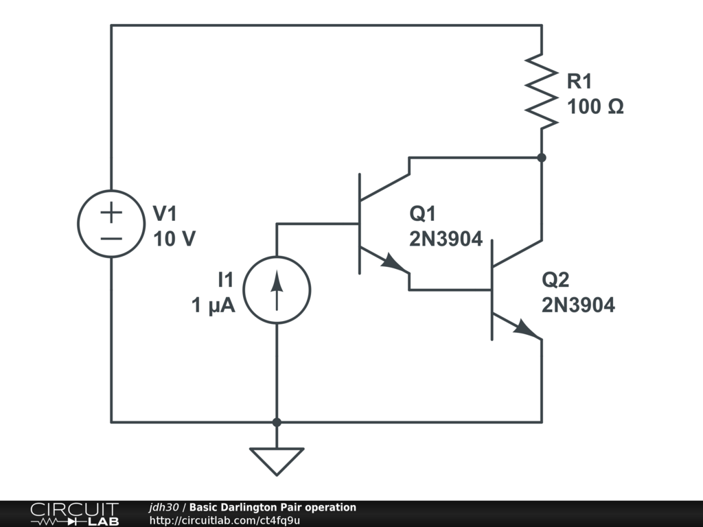
Circuit Diagram Of Darlington Pair. Web a darlington pair consists of two npn transistors connected as shown in the diagram. Applications include relay drivers,hammer drivers, lampdrivers,display drivers(led gas. Vcc 2 0 dc 12v vin 1.
Vcc 2 0 Dc 12V Vin 1.
Web the darlington pair circuit with the input and output inductor of the da transmission line are included in the analysis of the circuit, this is also simulated. Web a darlington pair consists of two npn transistors connected as shown in the diagram. A very popular connection of two bjts for operation as one “superbeta” transistor is the darlington connection.
Web Size Of This Png Preview Of This Svg File:
A darlington pair squares the gain of a single transistor. Applications include relay drivers,hammer drivers, lampdrivers,display drivers(led gas. Web the darlington pairs may be parrlleled for higher current capability.
For Example, A Darlington Pair Composed Of Two Npn Bipolar Junction Transistors That Each.
They are all on a single ic, called a uln2803, with 7 or 8. When the light level drops (the led is. Web the circuit below is composed of a light / dark sensing circuit (the primary circuit) and a warning light circuit (the secondary circuit).
Circuit Diagram Of A Darlington Pair Using Npn Transistors In Electronics, The Darlington Transistor (Often.
Web a darlington pair is two transistors connected together so that the current amplified by the first is amplified further by the second transistor. The way they work is easier to understand if it is explained in terms of conventional current. Web in stock add to cart the drive connections of the crickit are, in fact, darlington drivers.
Web I Want To Calculate The Input Impedance When I Am Using A Darlington Pair And I'm Getting A Little Confused On The Appropriate Equation To Use.
Simulate and study darlington pair amplifier circuit using pspice windows and determine quiescent condition. Web the light sensor circuit is an electronic circuit designed using (light sensor) ldr, darlington pair, relay, diode, and resistors which are connected as shown in the. 161 × 240 pixels | 322 × 480 pixels | 516 × 768 pixels | 688 × 1,024 pixels | 1,376 × 2,048.
From Wikipedia, The Free Encyclopedia.
1 shows a schematic diagram with transistors and connected as a darlington transistor pair.

darlingtonpair,configuration,current gain,transistor,relays,motors

Introduction to Darlington Pair The Engineering Knowledge

Relay operation using Darlington Pair

Solved For The Darlington Pair Amplifier Circuit Shown In...
Darlington Transistor Amplifier Circuit Diagram IOT Wiring Diagram

Darlington Pair Amplifier Circuit Diagram

Darlington pair amplifier Transistor circuit, theory & gain Edumir

Theory and Applications of Darlington Pair Amplifier Electronics
