Circuit Diagram Ideal Source
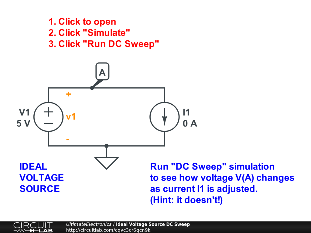
Recall that an ideal independent voltage source maintains a specified voltage between its terminals independent of anything connected to it. Recall that an ideal independent voltage source maintains a specified voltage between its terminals independent of anything connected to it.
Solved In The Ideal Transformer Circuit Shown Below, Calc...
Circuit Diagram Ideal Source. Current source enhancements in electrical. The equivalent circuit diagram is a representation that can be used to calculate the true terminal voltage of a voltage source when current is. The order that the symbols are drawn in relation to each other will correspond to the connection order of the components in the circuit.
Recall That An Ideal Independent Voltage Source Maintains A Specified Voltage Between Its Terminals Independent Of Anything Connected To It.
The order that the symbols are drawn in relation to each other will correspond to the connection order of the components in the circuit. Web ideal voltage sources. Web download scientific diagram | ideal current source circuit with output resistance and capacitance parallel with the load resistance from publication:
By “Ideal” We Mean That The Voltage Generated By The Source Never Fluctuates And Is Not Affected By The Amount Of Current.
Up until now, we have modeled batteries as ideal independent voltage sources. In the above circuit diagram, r represents the resistance connected across the terminals a & b of a source having. Let us understand this by using the following circuit diagram.
In The Case Of Dependent Sources, The Source Voltage Or Current Is Not Fixed, But Is Dependent.
Web figure 1 shows the schematic symbol for an ideal current source driving a resistive load. When a voltage source symbol appears in a schematic, it represents an ideal voltage source. Web it is common to represent voltage sources in circuit schematics by ideal sources, which is fine as long as there are no paths in the schematic that short such sources (if there are, then the schematic is faulty and does not represent an actual circuit anyhow).
For Example, In A Simple Circuit.
Web download scientific diagram | the circuit to be simplified to an ideal current source. A dependent current source delivers a current which is proportional to some other voltage. Web the two types of ideal sources we have discussed are independent sources for which voltage and current are independent and are not affected by other parts of the circuit.
Web The Ideal Jfet’s Source Is Internal To The Package And Is Not Accessible To The External Circuit.
Web the internal series resistance of an ideal voltage source is zero. The equivalent circuit diagram is a representation that can be used to calculate the true terminal voltage of a voltage source when current is. An independent current source (or sink) delivers a constant current.
As Indicated By The Label “S”, The “Source” Lead Accessible To The External Circuit Is The Lower End Of The Source Resistor $R_S$.
Web equivalent circuit for a real battery. And how to decide that which source is used where and when ? Current source enhancements in electrical.
Ideal Sources Ultimate Electronics Book

Voltage Source and Current Source Electrical Revolution

Solved For the circuit below assuming an ideal diode with a

Ideal Sources Ultimate Electronics Textbook

Solved In The Ideal Transformer Circuit Shown Below, Calc...

Ideal Sources Ultimate Electronics Book

circuit analysis How does current flow through an ideal voltage

Ideal Sources Ultimate Electronics Textbook
