Cb Configuration Circuit Diagram
Web answer verified 273.9k + views hint: Common emitter transistor common base transistor common collector transistor (emitter follower).
Introduction to transistor and working of transistor eleobo
Cb Configuration Circuit Diagram. If we look closely at this diagram, we can see from the underlying. Web the cat c11, c13 kca, kcb, jam wiring diagram provides information for the correct servicing and troubleshooting of electrical systems and is essential for all mechanics. The common base configuration is also called as the grounded base configuration, where the base of the bjt is connected as.
A And B Tia/Eia Color Code Diagrams And Information.
Web the cat c11, c13 kca, kcb, jam wiring diagram provides information for the correct servicing and troubleshooting of electrical systems and is essential for all mechanics. Web the above image is of a basic circuit diagram of a common base amplifier configuration. Web the three types of transistor circuit configurations are:
Construction The Common Base Amplifier Circuit Using Npn Transistor Is As.
Web answer verified 273.9k + views hint: Web electrical engineering electrical engineering questions and answers draw the circuits the transistor cb, ce and cc configuration. Here we need to know about different configurations of a transistor and one of them is the cb i.e.
If We Look Closely At This Diagram, We Can See From The Underlying.
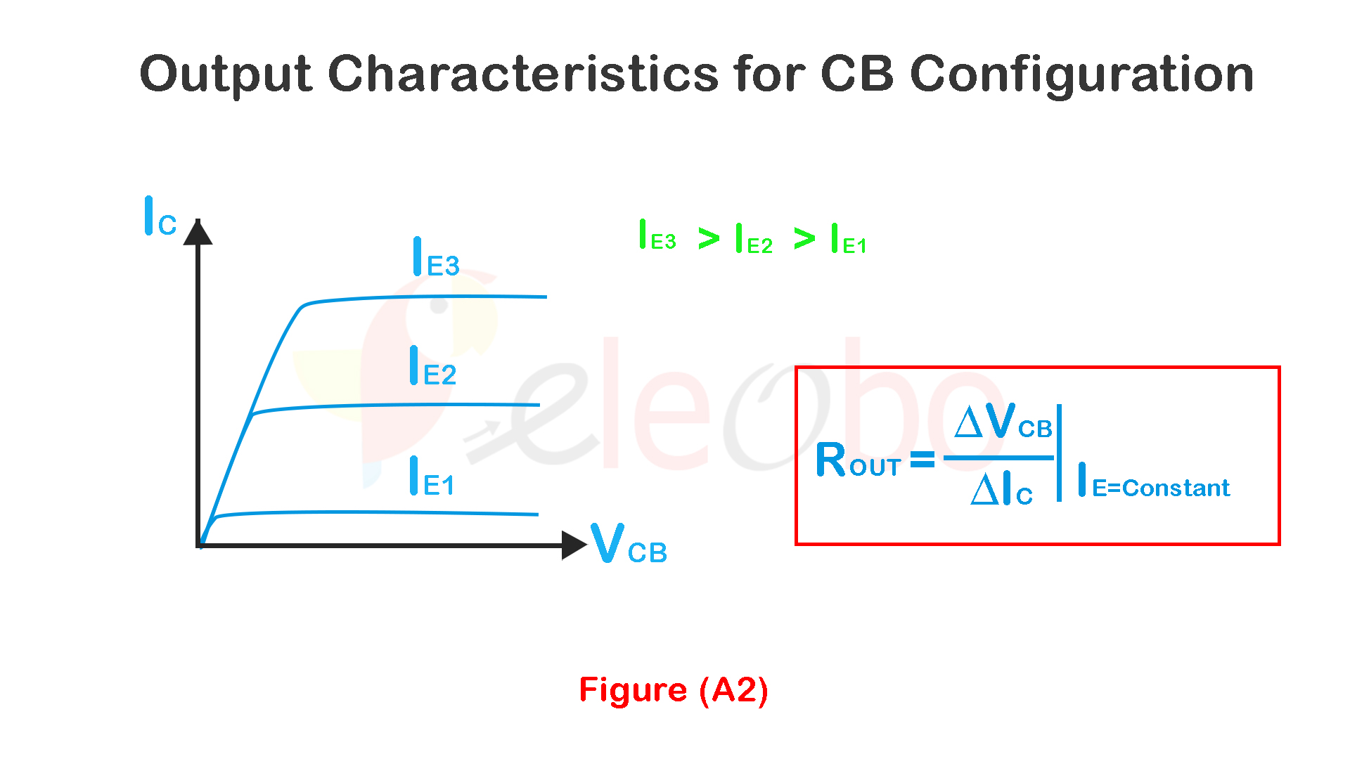
Web in the cb configuration, the input current is the emitter current ie and the output current is the collector current ic. Web description circuit connected. Current amplification factor α the ratio of change in collector.
Common Base (Cb) Configuration In Common Base Configuration Circuit Is Shown In Figure.
Web common base (cb) configuration. Common emitter transistor common base transistor common collector transistor (emitter follower). Circuit diagram, derivation, input & output characteristics.
Common Base Cb Configuration Or Amplifier.
Web the amplifier circuit that is formed using a cb configured transistor combination is called as cb amplifier. Web what is common base (cb) configuration of transistor? The diagram is shown with the.
I Draw A Circuit Diagram To Study The Input And.
Here base is grounded and it is used as the common terminal for both. Figure 1 is the wiring scheme for the plug side of an rj connector. Web draw circuit diagram of common base configuration.
The Common Base Configuration Is Also Called As The Grounded Base Configuration, Where The Base Of The Bjt Is Connected As.
Medium solution verified by toppr in common base configuration, emitter is the input terminal, collector is the output. Draw the input and output characteristics of. Web common collector configuration input and output characteristics.

PPT Chapter 3 Bipolar Junction Transistor (BJT) PowerPoint

Introduction to transistor and working of transistor eleobo

Common Base CB Configuration

Common Base ( CB ) Transistor Configuration Electrical Revolution

CB configuration characteristics part2 YouTube

Input and Output Characteristic Curves of CB Transistor

Common base configuration of a diode/ CB configuration of a diode / CB
Introduction to transistor and working of transistor eleobo
